Friday, April 29, 2011

Day 38

Today, I continued trying to fix the points jumping problem. I found a few causes and removed them. The main problem was the facet node with cusp polygon turned on. However, after removing all the facet nodes in my scene, the point numbers still continuing jumping.

Mr Ron told me to start searching where the problem was from the start. I found out that the problem was on the first voronoi fracture node that was used. Mr Ron asked me to use the same method he taught me yesterday to fix the problem. But after trying it, it still didn't work.

Below is how the hierarchy looks, (I did it in a new smaller file. )

Thursday, April 28, 2011

Day 37

Mr Douglas dropped by today. I showed him what I had done so far. Both the particles driven vortex that blows up the pre-fractured geometry. I told him of my intention of implementing that system into the original fracturing system. Mr Ron also helped me explained about what is going on in the scene and also above the point sop that calculates the area and also the copy loop. I also showed Mr Douglas the files hierarchy set up for the secondary fracture in the original fracture file. Just that the files are not ropped out completely so I couldn't did any tests.


I finally finished ropping out all the files. And after plugging in the necessary nodes, I proceed to did some tests. At first the bounding sphere starts to occur from frame 1 onwards, which I do not want. So I put a if expression to trigger the activation of the bounding sphere. Below is how it looks:


I also set up expressions on both the forces which drives the particles. To make things faster, I ropped out the simulation just before the popnetwork. The ropping took me 1 hour and 45minutes. However after ropping out and checking the points, The point numbers and points moved drastically. Hence, when I did my copy stamping, on the second frame of my simulation, the simulation screwed up. Below is how it looks:


I figure that the points are giving me the problems as my particles looked alright. I went back to the ropped out files and check the points and this is what I see:


My particles look like this:


I do not know why is it like that. Hope Mr Ron could help me fix it.

Day 36

Today, I continued working on the particles driven vortex field. I took Bryan's rock and decided to give it a try using the same system Mr Ron helped me built yesterday. I did exactly the same as what is done yesterday.

Below is the result:


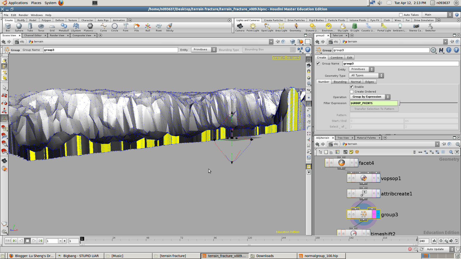
I then moved on by taking Bryan's new terrain which he was working on now, and reload it into my latest fracturing file. I had to do a lot of adjustments, such as the previous terrain was straight, but now it has bend. I got to bend the crack line to kind of match the terrain structure itself. Below is how it looks,

How it looks if I used back the old grid for the cracking line:

Before:


After:


Other than that, nothing much has been changed compared to the previous terrain. I didn't had time to enter into dops and did the voronoi fracturing. So I only had the cracked open terrain ready. Below is how it looks:


After that I proceed on to implementing the particles driven vortex field for the secondary fracture onto the actual terrain itself.

I encountered some problems in trying to get the bounding sphere to affect the group that was supposed to fracture.

I asked Mr Ron for help and he told me the reason I couldn't get it to work was because the point numbers of the pre-fracture geometries are changing every frame when its playing.

He helped me fixed it by using a locked null node to store the entire geometry area. He then used a measure tool to measure the entire area of the geometry in terms of primitives.


As you can see above, the locked null node and 2 measure nodes. The reason there is 2 measure nodes is because, one of them is measuring a moving geometry area and the other a static geometry.


After that 2 attribpromote nodes are used to convert the data which is in primitive, into points data.


A point node is then used to determine the actual area being used. The variable "area" is defined by the second input which is from the locked null for the fixed area above.

Then a scatter point is used to scatter the points in the group which was created much earlier and by the attribute "area":


A voronoi fracture node is then used to create the pre-fractured data for the geometry.

However, Mr Ron discovered a problem. There was a serious increase number of points below the hierarchy and much above. That was the source of the problem as the data the point node received from both inputs will not matching. 

Below is how much it changes,

After the dop network,


Before the dop network,


As it is shown there is almost 3 times more points in difference. 

After much searching, Mr Ron found the problem to be with the facet somewhere in the middle of the hierarchy. And inside the facet, because the option " Cusp Polygons" was turned on that is why the problem occured. Turning the facet node off, fixed the problem. But the problem is that I had to re- rop out everything. 


After re- ropping out everything, I proceeded on to do the secondary fracture. I realised that in the foreach node, each "piece" group has 2 pieces inside. And when I tried to create a point in the centre, it ends up creating a point in the middle of the 2 geometry piece. At first, I didn't realised that problem existed. But until I saw this:


I thought that it wasn't something major, so I proceeded on trying out the simulation. The simulation turns out to be incorrect. I realised that the points in the centre is causing the problem.

And in order to fix that problem, I got to change the voronoi fracture node up above the hierarchy to only one. That will definitely fix the problem as now 2 voronoi fracture nodes are creating replicate groups.
I got to re-rop out all the files once again. And I do not think I could even make it in time to show Mr Douglas tomorrow. Let's see how it goes.....

Wednesday, April 27, 2011

Day 35, continued....


What this argument does is it creates a copy loop through each piece of the pre-fracture geometries. When this argument is keyed in, there will be only a piece of the entire pre-fractured geometry in the viewport. If there is a need for visualisation, a copy sop could be used. Increasing the number of copies will copy back each geometry piece. A transform node is then used to bring the piece to the origin.

A popnetwork is also created just after the node that deletes everything except the points.

Inside the popnet,

As no emission of particles are needed, we just set the Impulse Birth Rate option to $NPT

$NPT = all point numbers.


A animated bounding sphere is used to group the particles.


And a force is used to blow the particles apart and another force to act as the gravity pushing the particles downwards.


Below is the render:

Monday, April 25, 2011

Day 35

Today, I continued doing the secondary fracturing and also researched on the circular force that blows pre-fractured geometries apart. Someone replied my post on the secondary fracture on odforce forum. He also provided me a file.

I looked through the file and I realised something. The secondary fracture that guy helped me set up is by adding a voronoi fracture configure object into my dops hierarchy. It provides me with very nice fracturing pieces and it also sort of fits the secondary fracture idea I was looking for. But Mr Ron said that that method is calculating the dynamics per frame which takes up more cache space. I agreed fully, as the cooking time increased by so much after it was added.

Out of curiousity, I would like to know why everyone likes to use the voronoi fracture configure object node even if its so heavy. Its like practically every file I get out there uses this node. Just curious though. And I wondered is it possible to replicate the same effect without using the voronoi fracture configure object node.

Below are 2 renders, one with the voronoi fracture configure object node and the other without.

Voronoi fracture configure object node:

 Without Voronoi fracture configure object node:


The scatter points and the voronoi fracture node is exactly the same. And the difference could be seen quite clearly. 

Below is the test I did yesterday and it was edited by someone from the odforce forum:
He helped me clean up my dops. Below is the screen shot:


Mr Ron suggested not using the voronoi fracture configure object node as it is calculating real time which takes much too much memory. He suggested increasing the scatter points instead.

 I also did the vortex field test as another way of blowing up the rock into smaller pieces. Below is my initial test:


Mr Ron helped me improve it even further. Instead of using the dops to blow up the pre-fractured pieces, He helped me did it in the pop network. 

Firstly, he added a point in the center of each piece.


Then the point is grouped:


Then the pre-fracture geometries are deleted:


Inside the pop network, a bounding sphere was used to animate the explosion effect. The particles are then grouped inside the bounding sphere. 
Then a force is applied to make the particles move:

Then the inside and outside groups are deleted from the voronoi fracture node. Mr Ron keyed in an argument:

What this argument does is it deletes everything in the

Day 34

I continued doing the secondary fracturing today. At first I tried grouping the pieces I want it to fracture again in a group:


Then I created a voronoi fracture node with the group I created earlier as the group to fracture. Then I went into the dops and did a basic fracturing hierarchy. Below is how it looks:


But it didn't turn out well. Below is the result:


I found a file on odforce which shows the different kinds of fracturing techniques and how they are done:

http://forums.odforce.net/index.php?/topic/9119-voronoi-dynamic-location-based-fracture-wip/page__st__216__p__73750&#entry73750

I opened the file and this is how it looks:


After playing through all of them. I found that the one which was closest to what I was looking for is the "glue fracture" fracturing.

Below is the dops hierarchy,


And how it looks:


Mr Ron asked me to research on how to create a circular explosion force. And also not using a polyreduce on the geometry.

Sunday, April 24, 2011

Day 33

Mr Douglas dropped by today. I showed him my half completed renders and my particle instancing. He said it was okay so far though. He was also very interested in my low poly to high poly switching files.

I asked him how do I proceed on from here. He told me to try and create secondary fractures to further enhance the whole effect. He told me a way to do it.

I can try putting maybe a rock on top of the terrain and when the terrain cracks, the rock can collide with the broken terrain pieces and further break it.

The method which I thought of also was using the group which was used to emit particles from and crack it further.

I haven't tried it yet. But I would on Monday.

Wednesday, April 20, 2011

Day 32

I started the renders today. The first render was the cracking dust. I set up that render and went for lunch. The render time was killing me. It takes about 20mins per frame and I left it to render for almost 7 hours. Fed up, I stopped it at frame 123.

Below is the result:

After that I started to render the terrain so that I can composite the dust and the terrain together. But when I tried to render the terrain, a black screen keeps occuring. And sometimes a piece of the terrain is shown in the MPlay window. I consulted Rap and he said maybe its because there wasn't any shader. He helped me did a simple shader and it works.

Below is the terrain render:

Tuesday, April 19, 2011

Day 32

Today I continued working on the dust render. But I kept encountering the same problem that I have experienced yesterday. The render came up looking like spheres and points.

I consulted Mr Ron on this and he helped me uncheck point instancing and the render works already.

Below is the before and after:


Mr Ron also took a look at my instancing file. He advised me that, the method I am using for the point instancing takes up too much time to cook. Hence, making the scene work slower. He helped me set up something which works the same way and also runs faster. Below is how the hierarchy looks,

And how the instancing looks,

Hierarchy:


This is the parameters view on the instance node on the geometry level. Mr Ron suggested that the instancing shouldn't be done here as there are limitations to what it can control.

He suggested doing on the point sop inside the geometry.


As you can see, at the bottom of the parameters view for the point sop, there is also an instance tab. The expression is then keyed in here.

I made 2 instanced objects:

Geometry 1:


This is made from a box and a mountain node.


Geometry 2:


This is created the same way.

Back to the expression, the expression " /obj/geo`$ID%2` " is keyed in.

What this expression does is, it gives the particle ID a alternate value of 0 or 1.

Then a new attribute seed is created. And the same expression is keyed in.

After that is done, as shown in the details view, the last column,


The particle ID is replaced by the variable seed. And after that, the instanced geometry is shown at the end.

particle ID 0 = instance/geo0
particle ID 1 = instance/geo1

Below is how it looks,

Monday, April 18, 2011

Day 31

Mr Ron dropped by today to check on our individual progress for 2 weeks. I showed him my progress. I also showed him the instancing test I did on friday. His advice was to work a little on the instancing and start rendering out the dust and putting it all together to see how it looks. I encountered some problems when I am rendering the dust out. I do not know why everytime when I tried to render out the sprites, there is this problem. I couldn't seem to find the reason why this is happening. Below is the image I kept getting:


This is the render I will get and sometimes I will get this render:


I do not know why is it like that, even though I made sure everything is set correctly.

Not knowing why is it like that, I did another test. I opened a new scene and imported the geometry into the new scene. Then I did the same thing I did in the previous file and it works!

Below is the composited render:


DUST RENDER
The dust render took about 15mins.

  TERRAIN RENDER

FINAL COMPOSITED RENDER

Although it works, but I would still like to know why that problem I explained about keeps occuring.

Friday, April 15, 2011

Day 30

Today I decided to work on the debris emission from the fracturing. My first idea was revolving around the foreach node. But after much trying, I realised it didn't work. After that I googled for "replacing particles with geometries". The search results came up with "instancing". Immediately I went in that direction.

Sidefx documentation on instancing:

http://www.sidefx.com/docs/houdini9.5/copy/instancing

http://www.sidefx.com/docs/houdini9.5/particles/instancing_rendering


I started giving it a try. But I encountered a problem. I couldn't view the instanced geometry at all in the viewport. I then did another search and people will talking on the forums that it is not possible to see instanced geometries in the viewport. Even sidefx documentation agreed on that. Below is how the starting test looks like:


This was all I could see from the test. I then did a test on the actual terrain and this is how it looks:


As you can see above, there is only particles even after I set up instance geometries. Below is how the hierarchy looks:


Not knowing why, I when to the forums and did more research, hopefully someone could have discussed it before. I found this thread which is almost the same as what I was talking about:

http://forums.odforce.net/index.php?/topic/10539-instancing-crowd-animation/page__hl__instancing__fromsearch__1


I downloaded the hip file and decided to look at it. Below is how it looks,


This file is actually a crowd simulation of ants crawling. Below is the different hierarchies involved:


Instanced geometry:


The ant is modelled procedurally modelled in houdini.

Particle Instancer:


This is a simple particle emission simulation.

Copy Stamping:


This is copy stamping the geometry to the particles system.

After understanding how it all works, I did a test on the real terrain. Below is how it looks:


Ways to improve:
1: Reduce amount of particles emitting.
2:Time the particles to emit earlier

I did exactly the same as the ant file I downloaded from the forum. And it works!

We also saw Mr Ron today after 2 weeks. He took a brief glance at what we were doing and told us to update our blogs.

Thursday, April 14, 2011

Day 29

Today Mr Douglas dropped by. I showed him the particles emission and my progress. He said that it was okay so far. I also asked him how to emit particles when the fracture piece breaks apart. Mr Douglas gave me a suggestion to group the falling geometry pieces by their Y value. Then emit particles from that group.

Mr Michael gave me a suggestion to try grouping them according to their velocity value. In the end I tried both methods and the grouping the falling geometry pieces by their velocity seemed to work.

Below is how it looks:

Wednesday, April 13, 2011

Day 28

Today I continued working on the particles emission, but this time for the fracturing. I am emitting particles from the inside group of the voronoi fracture. But when I put a delete node after the dopnetwork to retrieve the inside group, the inside group went missing. Not knowing why, I posted on forums asking for help.

http://forums.odforce.net/index.php?/topic/13015-getting-the-inside-group-out-from-voronoi-fracture-node/

Someone replied and told me that it is because I had a clean node inside my hierarchy and that deletes away the inside group. That is the reason I couldn't get the group out. Below is the problem and the solution:


After getting the inside group out, I went on to the particle emission. I wanted the particles to emit only after it starts to fall but I do not know how to start. Hence, I consulted Rap on how to tackle this problem. Rap told me that he knows how to emit particles from the collapsing piece when it falls within a boundingbox. He helped me set it up. Below it's how it looks:

It is a good start for me and I will see how it could proceed later on.

Hopefully I could compile both the cracking open particles and fracturing particles by today so that it can be shown. The scene is too laggy and ropping out bgeos are taking a long time.

Monday, April 11, 2011

Day 27

Today I continued working on the particles. I consulted jiabao on how to group the points without using a bounding box. He told me that I could just drag the points that I want to group and group them according to pattern, but it isn't that procedural. He also gave me some directions that I could work on, like grouping the points according to their normals. He asked me to post on the forums to get some lead on how it works.

Finally, I received a reply from some one on sidefx forum. He did a demonstration on how to group them using dot-product.

Below is how it looks:


And this is how it looks inside the VOP SOP:

 I then tried applying it to my terrain. I got it to work somehow. But the problem is, it wasn't easy to control at all. Firstly there are other points which I do not want but they have the same normal direction as the points I wanted. If I tried to increase the magnitude of the vector, it will select other geometries that I do not want.


Below is how it looks:

Magnitude of Vector: 5


Magnitude of Vector: 10


Magnitude of Vector: 15


As you can see in the above picture, the points which I do not want are included in the selection. The points that I want is still not yet selected fully. This method is fully procedural though, but I think that it can't be used in this situation. But is a valuable knowledge which can be applied in further.

By right I want it to look like that:


This is done by draggin the points and doing a group by pattern. But this way isn't procedural though.

Below is how the dust look for the cracking earth open: