Thursday, May 26, 2011

Day 54

Today, I continued working on the rocks layer interaction.


However, I encountered a collision issue with the terrain. The arc that broke apart doesn't collide with the terrain. It just goes through it.

Below is how it looks,


The video,


I tried all kinds of method, I also did a test using a sphere, it worked through.

Below is how it looks,


Out of a sudden, I do not know what did I do and suddenly it worked. But the pieces are behaving quite crazily.


I then proceed on trying to delete the sphere after the dopnetwork. There seem to be an issue if I'm gonna do it procedurally. The issue is because, the groups get all totally renamed into something else. And the problem is I do not know which is the group that is the sphere.


Mr Michael suggested doing it the manual way, which is just drag over the sphere and delete in the viewport. It somehow worked.

Before:


 After:


I did a simulation to check if it collides and it seems like it does. I then happily went and did a rop.


 Little did I know that there is a huge problem awaiting me....

I then did a playblast of the result. This is what I get:


As you can see, there are a couple of serious issues that needs to be dealt with.

1) The erratic behaviour of the arc pieces colliding.
2) The spheres which appears at the back for no particular reason.

I consulted Jia bao on problem 2 first, he told me that I needed to turn off the display flag of the sphere before I do my rop. But the thing is I did my sphere, dops inside the geometry level, which doesn't have the display flag for it.

He helped me try to put a ends node at the end of the sphere and hopefully it will be seen as wireframe and it will not render out as a object. But unfortunately it didn't worked. He pointed to me Peter Quint's fracturing file as a reference. I will not dive into the scene but it should look familiar,


After browsing through, I decided to redo my entire dops in the scene level. I did it in a entire new file, hopefully it will help make things work and speed up the whole scene.


I somehow manage to delete the sphere using the procedural way. But however, I have problems with the collisions.


Below are some test simulations which are screwed.


I also realised that all rocks even arcs present in the scene have to have a initial gravity acting on it and they had to be all dynamic objects, if not when the pieces are falling, the rocks will float in mid-air. That proved to be a major issue as all the rocks and arc are interpenetrating the terrain, which makes converting them into dynamic objects harder.


It is 4am in the morning now. And until now, I haven't even had a single problem solved. I decided to do one last test and if it still doesn't work, I will scrape the entire idea of the rocks and arc on the terrain.

The last test:


Okay, so officially it doesn't work. Screw it man!

So now, I will scrape the entire idea like promised. I then went over and rop out the terrain simulations with the falling pieces with a color node and a vertex node to clean the fracture lines.

After that, I went into Jia Bao's lighting file and update the new files inside and did a test render. At first, it didn't show anything but after some debugging, It worked.


At 4.45am, I officially put it to render. I then went to sleep. God knows when it will finish rendering.


Back tracking now!


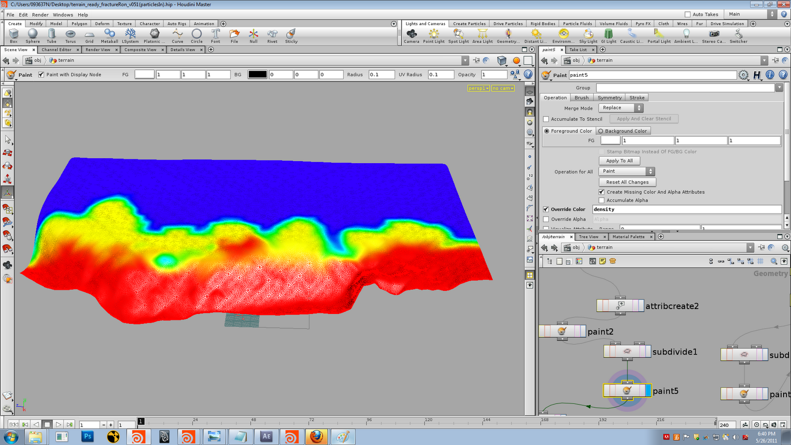
Earlier in the day, I encountered a up-resing issue for my terrain. At that point of time, Mr TK and Mr Michael was around and I brought up the problem to them. Mr TK suggested upresing the paint node and then using another paint node to show the up-resed paint data.

It worked! I double confirmed with Mr Ron regarding that up-resing method, and he said it will work.

Unfortunately, I will not be using this method for the final video on Friday.

Before:


After:

Monday, May 23, 2011

Day 53

Today, I went on to add the arc and rocks and stuffs into the scene. Today, I came in and checked that my ropping of the bgeos sequences after the dopnetwork were done. Luckily. Initially, I started on the particles for the pieces falling down. I used a dopimport node to get the velocity attribute out from the dopnetwork. I then group points according to the velocity attribute in Y direction.


The group node:


I tried running it into the popnetwork immediately after this node, but it is INSANELY  slow. So I decided to rop it out. And the rop took me until Mr Ron came by for a review, which is almost 3 hours later and it is not even half way there. As Mr Ron was here, I canceled the ropping. I asked Mr Ron regarding about overlaying another simulation over the existing. He told me it was very easy, just bring in the other geometry pieces as static objects and make them fall inside dops.


He helped me optimised a terrain proxy to calculate the collisions of the extra geometries. He also helped me did a little demo on how to go about doing it. After that, I told him, I will give it a try regarding overlaying the simulations.


First, I rop out separate bgeos for the different rocks.


I then imported them separately into the scene.

Inside the scene, I decided which rock I want it to break apart, and I did a fracturing system for each of them separately.

I picked the arc first,


I will not go into the minor details, as this has been taught to me way back. Anyways, what is going on here in this hierarchy is, basically I am painting the pieces size on the geometry itself.


After this, I used a sphere to break it all apart inside dops.


Inside the dops, I imported the arc as a rbdfractureobject, and the sphere as a rbdobject. I then did a simple system after that and the result is that it breaks. I could also tweak the timing of the breaking, just by tweaking the sphere timing. I then hid the sphere. I then did a dopimport to bring the simulation out from the dopnetwork.

This is how it looks:


I then decided to do the breaking for another rock. I used exactly the same network to tackle this problem and the result is shown below:


I left the grouping of points based on velocity data bgeos sequence to rop overnight. Hopefully nothing will be wrong with it tomorrow.

Saturday, May 21, 2011

Day 52

Today, I started doing the dust emission from the terrain cracking. I emit particles at the edges of both terrain and add a gravity node for it to fall down. The color is also tweaked to the same as the terrain itself. As the earlier method to select the points procedurally didn't really work out, I went and selected the points individually. I then group them together and emit points based on that group. I also did a render of the entire terrain sequence.


I then did a render of the dust in a separate layer but when I tried to composite it, The position were totally off. I haven't got a chance to figure that out.

I spend the day ropping out the remainder of the dynamics bgeos sequences.

Thursday, May 19, 2011

Day 50

Mr Douglas dropped by today to check on our progress. I showed him the bgeo sequence I playblasted, with the pieces falling. He said it looks alright. The delayed load shader also works well for the render.


I heard some comments regarding the fracturing and I decided to fix them one by one.

1: The opening of the earth seems too wide.
2: The falling pieces are too big.
3: The terrain thickness should be much more.

For 1st comment, I went into the point node and tweak the multiplier lower,


For 2nd comment, I went into the crackmap and painted more on the edges and increase the scatter points to make the pieces smaller.


For the 3rd comment. I increased the extrudevolume node a lot more, to cover up the thickness of the terrain. 

I spend the day re-ropping out all the bgeo sequences.

Wednesday, May 18, 2011

Day 49

I started doing the cracking on the commercial version of Houdini using the new method Mr Ron told me about on Monday. I re-created everything the same way. I fused the points before the merge node. After doing that,  I re-create the groups using the new naming convention. Then I did the animated box coloring the terrain. I then pass it through another foreach to do the attribute promote. From here onwards, It became much slower. Hopefully, it will work though.

Tuesday, May 17, 2011

Day 48

Today, I continued doing what I am supposed to do. Below is the playblast of the cracking only:


While, I was still working on it, Mr Ron dropped by in the late morning, he told me he had an awesome idea, that will put all the research I did for the past 1 month plus to waste.

First, he created a foreach node after the point node to fuse up the points for each piece of the pre-fractured geometry.


It is repeated for both sides. Then a merge node is used. After that the groups are cleaned up and renamed to a matching naming convention for both left and right piece.


The clean node removes all the existing groups, connectivity creates a new attribute and connects the similar data type together. Partition node creates a new group based on the new attribute created earlier. Then after making sure the groups and primitive numbers are correct, We proceed on.

Before that, Mr Ron told me that, previously I used the facet node to clean up the pre-fractured pieces, which does the job, but that in turns increased the number of points which is not desired. Mr Ron told me that there is another node that I could use which does the same job but does not increase point numbers is the vertex node.


Under the vertex node, the last option is switched on to "Cusp Normal" and there is a slider for tweaking. However, due to some display issues, the sliders needs to be reset first before it will work. The way to reset it is to drag it to 0 first before dragging it on to the value desired.

However, there will be some black "stuff " on the object itself after using the node, but it is alright, just some display issues. The render looks perfectly fine.


This is how the display looks:


And the render:


(It is super low resolution, but you know what I mean though)


Mr Ron then told me what will happen next, which will blow my mind away, before he proceeds on. He told me that instead of using all the vopsop, copy loop and stuffs. He said that instancing would be a much better option.

How it will go about is that, the low resolution terrain will be used for the dynamic simulation, then from the dopnetwork, he will export out the data as points. Then he will instance the high resolution pieces onto the points and it can be rendered from there. This way, the whole simulation will be so so fast and the render fast too.

Firstly, since the initial simulation was done, he brought the whole thing into dops. As this was a test for proof of concept, Mr Ron just created a random fit expression for the velocity option under the rbdfracturedobject. This is how it looks with that expression alone:


Then a rbdsolver is used followed by a gravity node. Then after that, a dopimport node is used to import back the fracturing data as points data.


It looks like this in the viewport:


After that, We proceeded on to create the high resolution pieces that will be used for instancing. After changing the resolution of the terrain above, Everything else is the same thing. Until after the merge node,
A null is used to lock the position of the terrain, to not let it move.


Then a delete node is used to delete everything but a piece of the pre-fractured geometry. A expression is used to allow the delete node to change the piece of geometry it keeps per frame. That will result in a animation of pieces of pre-fractured geometry moving around.

Below is how it looks:


And how it look when it plays:


After that we ropped out the bgeo sequence of that. Then Mr Ron created a instance node on the scene level. Inside, a dopimport node is used to import the point data from the dop network. Then a material node is used. What it does is assign the shader to the terrain itself. But actually, a delay load shader is needed in this case. The "file" parameter from the delayed load shader is extracted out, and the bgeo sequence of each piece is assigned to it.


The expression used in this case is $HIP/high/high.$ID.bgeo

It looks like a simple root file, but what the $ID does is shown below:


The number at the end of the dopobject is the same as the id number of each piece. Hence $ID is used to represent the instanced dopobject for each piece.

The overall result is shown below:


Although it is quite difficult to see here, but it works. And I didn't even need to turn on the geo1 node which contains everything.

Sunday, May 15, 2011

Day 47

Today I went commercial for my cracking. I spend the day to redo my entire file in the commercial version. I requested for jia bao file, which contains the texturing and lighting. I was surprised as his scene has so many nodes. And I needed to rop out everything in a single node. I consulted Mr Ron regarding that, he tried converting all the lights in the scene into an otl at first, but it failed because the lights has references from elsewhere. Lastly, he introduced bundle to me. How it works is, it is something like a group and you can put everything inside a group, but the cool thing is, the group can be referenced anywhere.

After setting up all the bundles for the terrain, lights, rocks, etc. He created a new geometry container, and created a object merge node. He then brought in all the bundles and he asked me to rop it all out.

I decided to rop out the entire sequence first, then copy the shader over to the new file. However, after ropping out, I copied the shader over, and tried to render it, there seems to be a problem. I keep getting black screen in the render. Not knowing why, I consulted jia bao. At last, he fixed it for me, by removing the material under the geometry container. It somehow works though. He also told me that the arc and rocks positions weren't finalized yet. So I thought it would be safer to do it on the original terrain first. I managed to finish the cracking today though.


Cracking:

At first I managed to create the crack nicely. However, it is opening up in the wrong direction.


Not knowing why, I tried many variations but to no avail. I consulted Mr Michael, who was around at the moment. After much reasoning from him, he managed to get it to work. It was just playing around with the expressions.

Below is the expression which opens the crack the wrong way:


And the right way:


I will continue working on the file on Monday.

Wednesday, May 11, 2011

Day 46

Today Mr Douglas dropped by. I decided to only show him the method Mr Ron showed me yesterday as the previous methods weren't that good as the entire simulation takes too slow. Mr Douglas said the method used in this case was good and it makes the scene much faster. However, yesterday Mr Ron left the last part for me to find out as previously the final result turns out to be like that:


I decided to post it up on odforce to get some help regarding this, and thank god, someone replied and solved it for me.

http://forums.odforce.net/index.php?/topic/13202-vops-problem/page__gopid__82608&#entry82608


Now, I will document what exactly goes on in the file:

Firstly, the first fracture system is done using the usual way.

The difference starts with the first voronoi fracture node.

There is a option under the voronoi fracture node, attributes tab, called Keep Internal Attributes.

Mr Ron checked that, and under primitive piece, keyed in "piece"

What that does is it stores the data each piece has, and the scatter points will follow that set of data throughout the entire simulation


 After that, inside the dops.


I once asked Mr Ron if it is possible to trigger the fracturing without having any collisions. He said it was possible, and this is how it works,

He created random velocities to make the pieces fall apart differently.

The expression used was,

fit01(rand($OBJ),-1,1)*10 for Vx
fit01(rand($OBJ/2),-1,1)*10 for Vy
fit01(rand($OBJ+2),-1,1)*10 for Vz

What the expressions does is that, it takes a random value for the object and the value is then fit into a value range of -1 to 1. The multiplication is to increase the  overall velocity. While the division and addition of numbers to the object is to give it more variance.

At the end, this is how it looks:


Next, A timeshift node is used to lock the simulation at its first frame. Then a foreach node is used to add another layer of fracture points on the already pre-fractured piece. First, we need to make sure that the attribute piece needs to have point data so that the scatter points could reference that set of data. Hence, an attribute promote node is used to first convert the primitive data to detail. Then the scatter point is applied. After the scatter point, a attribute promote node is used to convert the detail data into point data. Then a voronoi fracture node is used at the end.


Then, a dopimport node is used to bring back only the point data from the dops.


A vopsop is used to copy the geometry data onto the points.

A copy sop wasn't used because, firstly it is too slow and a copy sop aligns geometry based on normal positions.

The vopsop in this case, aligns the geometry based on a rotation matrix.


First, we create the parameter "piece", then the attributes orient and P(point position) is imported inside. The orient matrix is then converted into a quaternion matrix.( rotation matrix with a angle) It is then multiplied with the original point position and added to the calculated point position from the dops. The output looks like this:


After making sure it looks good, Mr Ron created new groups for each piece. First he removed all the groups using a clean node.


Then a connectivity node is used to connect similar attributes class and output a new attribute. Then a partition sop is used to create a new group based on the new attributes.


After that, We went into foreach again to create a point in the center of each secondary pre-fractured geometry piece.


What this does is, it adds a point in the center of each piece and then put the new point in a group. The node "attributecreate_piece" creates the "piece" attributes and then stamps the foreach data.

Then after that, he splits up the group, one of the point data, and the other for the geometry data.


For the points side, I brought it into a popnetwork. Everything else was the same as previous.


A group node is used to group the points after it reaches a certain value. For the particles that didn't reached the assigned values, It will be stored in a new group.


For those particles that didn't managed to reach the assigned values, a position node is used to calculate the original point position.


A force is used to drive the particles apart.

Mr Ron said that we needed the orient attribute to copy the geometry piece onto the point data. But the popnetwork doesn't have. It reads velocity and normals values first. As we needed the orient attribute, Mr Ron made one using a vopsop.


What it does inside is, He is normalising the point velocitiy attribute. Then what the lookat node does is, it reads the normals of the point velocity and outputs it in a 3 x 3 matrix. Then he converts it into a quaternion matrix, then the attribute "orient" is connected to it.

It works though, next step, to copy the geometry on to the particles point data.

It didn't really work at first though. But anyways, it looks like this:


It is the same vopsop that is used to copy the geometry to the points earlier. But the result turns out to be like that,


I posted on the forum and I was given help.

What was new inside:


The difference is, the new point position is subtracted with the original point position. And then it is multiplied with the calculated point position. The result turns out to be like this:


And the playblast simulation:

Day 45

Today, I continued working on the same problem. Until now, no solution. And problem still persists. I didn't do anything productive today, I only did a rop out of the simulation after the vopsop node. And just plain doing that took me at least 4hours. And it failed when it is almost done.

I decided to use what I had rop out and when into the popnetwork. Inside the popnetwork, I just did a source with a bounding sphere group and just that the simulation took ages to cook.

Hence, the rest of my day is just spend waiting for the simulation to cook, and the speed is taking to cook is so slow until I couldn't even do any tweaking.


I don't think I will have anything constructive to show tomorrow to Mr Douglas except the latest method Mr Ron helped me with but it is not done.

Tuesday, May 10, 2011

Day 44

Today I continued fixing the problem. Mr Ron dropped by today also to help me fix it. I will do a recap of what he d

Mr Ron was running some tests still. No matter what he did the point numbers still continued jumping and behaving very strangely.

He then made a discovery, the pieces falling down from the pre-fracture geometry is not complete. Below is how it looks:


He advised me to re-do the whole scene as that may be the source of the whole problem.

But before that, he suggested trying to do a popnetwork inside the foreach node. Meaning we are birthing particles from each piece instead of the whole pre-fractured geometry.

He wanted the particles to start birthing after a certain time frame. And to determine that will be based on the point position of each point.


A vopsop is used to achieve that. First a vectorfloat node is plugged into the point position. Then a compare node is used to check if the point position value falls below the minimum set up in the node. If it falls below, it will store the point into the zero parameter, and if it is above the minimum, it will store the point into the go parameter. A switch node is used to switch between inputs when needed. After that, all data will be stored in the start parameter.


Below is how it looks now, in the details view:


The start parameter will then be used to drive the birth of the particles.


Under the impulse activation option.


For now, Mr Ron helped me till here, while I needed to redo my file. He asked me to consult him until I reached this stage in my new file.


NEW FILE

I used back the same old file which Mr Ron helped me fix the points problem. I didn't did it in the commercial version, because I wanted to fix that problem first, and using the actual terrain will make my whole scene even slower. Hence, I stuck with a simple grid.


I will continue from where I left of last time:

I fixed the problem by doing a separate voronoi fracture for each side of the grid and also before the point sop that opens up the terrain with an expression.

After that I proceeded with adding a box, to color the pieces which will fall down, and after that for the foreach node, I had to do it separately for the left and right side, as their pieces are named totally differently.


I then went into dops. However inside dops for some unknown reason, the pieces doesn't fall after being colored by the box. I was presuming this was the problem:


I asked Mr Ron why is it like that, I also explained to him about the mutiple groups thing on the whole geometry. He advised me to remake the groups before I enter into dops, therefore, I don't have to worry about multiple groups. He helped me did it,

What he did was first,


He used a clean node to delete all the existing groups. Then he used a connectivity node to connect all the primitives together into a attribute. Then he used a partition node to create the group and name the pieces. After the groups were re-created, it is then brought into dops.

Luckily, when I brought it into dops, it worked! Then I just did the same thing with the foreach after the dops. I brought in a piece of the entire geometry, pre-fractured it, added a point in the center of each piece. I also added the vopsop that was created in the previous file inside.